M3板设计

2011年3月09日 22:46

    都好久没上过博客,好久没写过咯,原因真的好懒好懒,最近又是那么的没目标,也不完全没吧就是打算做完这块板就辞职了,离开这座喧闹的城市,去个安静的地方静一下,做做自己该去做的事,也想去磨练磨练自己吧。或许以后一个人会很艰难,但自己决定的就得走下去这一条路。切不说出去闯的事,还有一个半月,努力把这板做好。

STM32F107VC 是意法的一款ARM Cortex-M3的MCU。不懂的谷歌、百度去。                                                                                                  这东西还做了挺久的,12月份就计划做了,现在才把方案整体原理图给定下来,导封装到画板也要费上不少时间啊,天天都熬点夜+偷点懒。好久没写过程序了,好不爽快啊,好像真的完全搞到只做硬件了。

     整体设计如下,以端口类型分类,各类总线分别输出方式分类,接出一ADC 一DAC。另外带TFT 触屏一块,好玩的地方在于加入了三轴加速度传感器,和DS18B20温度传感器,其实还想加别的传感器,但传感器的价格很贵,DS18B20这么常用的也要12块一个。另外还保留了了一组PE做16位的数据外扩,以及没用到的IO口做控制IO

发原理图

MCU主控部分,带入USB OTG模式

BUS篇,其基本带的总线资源都在这了

107的特别之处在于支持NET模式,RMII/MII 都支持,我当然选择最不好搞的RMII 也是最好的啦

各类杂七杂八的东西 还有PWM 

下次发就等到把板话出来了,加油


EEPROM都知道,做单片机的都知道EEPROM是什么东西,或许一说到很多人都会想到24C02这片子,但这东西只有2K,而且与单片机分离的IC传输速度明显较慢。 另外很多初学者可能认为数据就这么传进EEPROM就算是完成任务了,但实际EEPROM并不是这么用着的,以一片EEPROM 资料称能存储10万次的算,假若程序设置的是一秒一次存储,3600S/h  30个小时就做了108000次存储,基本达到报废这EEPROM的条件了。所以EEPROM 一般是做存储的数据保存后,产品需要做断电存储的功能,这样才能实现再次启动产品后使用上一次状态中的数据。因此EEPROM的存储设定要有条件式的触发。

在我最近做的一个小项目中,客户要求希望产品能在断电后的再次上电后做断电前的动作,这样断电便成了这个存储的触发条件,断电后的供电模式有两种一种是电池式供电,一种采用大电容供电。存储数据量小的话当然是电容供电的更好啦。然而这又会出现断电后的一个低压工作问题,一般5V单片机最低工作电压能有3.8左右。但EEPROM通常需要4.1V以上,这样片外存储的时间很可能会跟不上。如今单片机很多都集成了片内存储的EEPROM,存储速度远远高于片外存储十几倍,电容放电的瞬间完全可以胜任。网上实在太少这方面的资料和例子了,琢磨了一番STC的几个单片机后发现同一品牌的单片机内部EEPROM存储模式打进相同。在这我就放出一个STC 单片机内部EEPROM的例子,童鞋们可以根据片内的寄存器与相应的控制位修改即可使用,强调这只能使用与STC的 一部分单片机,主要有STC11FXX 系列、STC10FXX系列、STC125AXX系列、STC89C5X系列....... 其他的没试过,但只要对比资料结构大体相同都可使用。

贴程序:

 我这是做成一个头文件方便使用的

ifndef __EEPROM_H__
#define __EEPROM_H__

#include<reg51.h>
#include <intrins.h>

#define uchar unsigned char  
#define uint unsigned int 

sfr ISP_DATA = 0XC2;
sfr	ISP_ADDH = 0XC3;
sfr ISP_ADDL = 0XC4;
sfr ISP_CMD  = 0XC5;
sfr ISP_TRIG = 0XC6;
sfr ISP_CONTR= 0XC7;

#define RED_ISP 0X01
#define WITE_ISP 0x02
#define ERASE_ISP 0X03

#define MCU_CLOCK_5MHz 0x04
#define MCU_CLOCK_12MHz 0x03
#define MCU_CLOCK_20MHz 0x02
#define MCU_CLOCK_24MHz 0x01


/****************************************
打开ISP
*****************************************/

extern void ISP_EN(void)
{
	EA=0;
	ISP_CONTR=ISP_CONTR&0x08;
	ISP_CONTR=ISP_CONTR|MCU_CLOCK_12MHz;
	ISP_CONTR=ISP_CONTR|0x80;

}
/****************************************
关闭ISP
*****************************************/
extern void ISP_DIS(void)
{
	ISP_CONTR=ISP_CONTR&0x07;
	ISP_TRIG=0X00;
}

/****************************************
读取一BYTE
*****************************************/
extern uchar  Read_ISP(uint bite_addr)
{
	uchar DATA;
	ISP_ADDH=(uchar)(bite_addr>>8);
	ISP_ADDL=(uchar)(bite_addr&0x00ff);

	ISP_CMD=ISP_CMD&0xF8;
	ISP_CMD=ISP_CMD|RED_ISP;

	ISP_EN();

	ISP_TRIG=0X5A;
	ISP_TRIG=0XA5;
	_nop_();
	_nop_();
	ISP_DIS();

	DATA=ISP_DATA;
	return DATA;

}

/****************************************
写入一BYTE
*****************************************/
extern void Write_ISP (uint bite_addr,uchar DATA)
{
	
	ISP_ADDH=(uchar)(bite_addr>>8);
	ISP_ADDL=(uchar)(bite_addr&0x00ff);

	ISP_CMD=ISP_CMD&0xF8;
	ISP_CMD=ISP_CMD|WITE_ISP;
	ISP_DATA=DATA;

	ISP_EN();

	ISP_TRIG=0X5A;
	ISP_TRIG=0XA5;
	_nop_();
	_nop_();
	ISP_DIS();
	
}

/****************************************
擦除扇区
*****************************************/
extern void ERASE(uint addr)
{
	ISP_ADDH=(uchar)(addr>>8);
	ISP_ADDL=0x00;

	ISP_CMD=ISP_CMD&0xF8;
	ISP_CMD=ISP_CMD|ERASE_ISP;

	ISP_EN();

	ISP_TRIG=0X5A;
	ISP_TRIG=0XA5;
	_nop_();
	_nop_();
	ISP_DIS();
	
	
}

/*****************************************
连续写入
******************************************/
extern void Write_FLASH(uint bit_addr,uchar count,uchar *dat)
{
	uchar i;
	uchar add;
	add=bit_addr;
	ERASE(bit_addr);
	for(i=0;i<count;i++)
	{
	 Write_ISP(add,*dat);
	 dat++;
	 add++;
	}

}

#endif 

毕业设计后记

2010年6月19日 18:14

由于时间加之蛮多烦人的事,好久没上来了,懒了不少呢。毕业设计的网络设计没做成,时间太紧急了,而且这个做起来还是蛮复杂的,最后不得不在这个模型基础上做修改,改成了无线温度收集的小系统


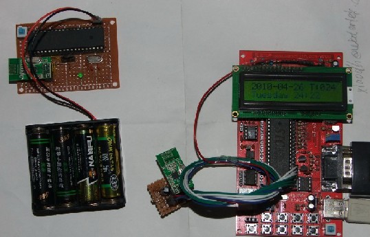
电池供电的那个小模块 中间黑色的小东西就是温度传感器 DS18B20 ,单总线数据输出模式

Init_DS18B20(void)//初始化ds1820
{
  
    DQ = 1;      //DQ复位
    delayus(8);    //稍做延时

    DQ = 0;      //单片机将DQ拉低
    delayus(90);  //精确延时 大于 480us

    DQ = 1;      //拉高总线
    delayus(8);

    presence = DQ;    //如果=0则初始化成功 =1则初始化失败
    delayus(100);
    DQ = 1; 
    
    return(presence); //返回信号,0=presence,1= no presence
}


ReadOneChar(void)//读一个字节
{
unsigned char i = 0;
unsigned char dat = 0;

for (i = 8; i > 0; i--)
  {
    DQ = 0;                // 给脉冲信号
    dat >>= 1;
    DQ = 1;                // 给脉冲信号

    if(DQ)
    dat |= 0x80;
    delayus(4);
  }

    return (dat);
}

WriteOneChar(unsigned char dat)//写一个字节
{
  unsigned char i = 0;
  for (i = 8; i > 0; i--)
  {
    DQ = 0;
    DQ = dat&0x01;
    delayus(5);

    DQ = 1;
    dat>>=1;
  }
}


Read_Temperature(void)//读取温度
{
  Init_DS18B20();
  if(presence!=1)         
  {
   
    WriteOneChar(0xCC);  // 跳过读序号列号的操作
    WriteOneChar(0x44);  // 启动温度转换

    Init_DS18B20();
    WriteOneChar(0xCC);  //跳过读序号列号的操作
    WriteOneChar(0xBE);  //读取温度寄存器

    NUM[0]= ReadOneChar();  //温度低8位
    NUM[1] = ReadOneChar();  //温度高8位 
  }
}

给出 DS18B20的 读写代码,若是单总线上有多个传感器那么读取温度里的 就不能跳过读取序列号操作了,毕竟要区分开数据是那个传感器的嘛,这里要说明一下的是DS18B20 每一个出场的ID号都不会一样的

毕业设计也不多说了,只讲到这里。下一篇讲一讲我最近做的一个小项目

毕业设计2:传感器无线网络

2010年4月12日 08:08

     离上次发毕业设计日志已经都好一段时间了,还是没啥大进展,懒了很多。当中有两天回了学校,有一天去了面试。工作还是要找D ,不然没法活了,当然面试还是......  继续呆家吧

弄了一下STC12C5A32S2 的内带AD ,方便当然方便过0809这东西啦。

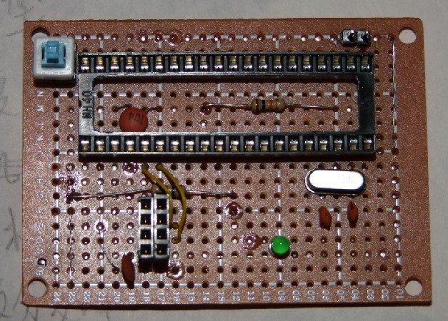
        几天没怎么工作过了~ 忙了一个下午到晚上,准备无线模块的整体弄了一下,焊好了

精致小巧,哈哈。其实也就没啥东西,就单片机,引接口出来接那无线模块而已 ,不过用的是电池供电,还好4节5号电池也 就6V不到的样子,电源部分不用怎么整它。

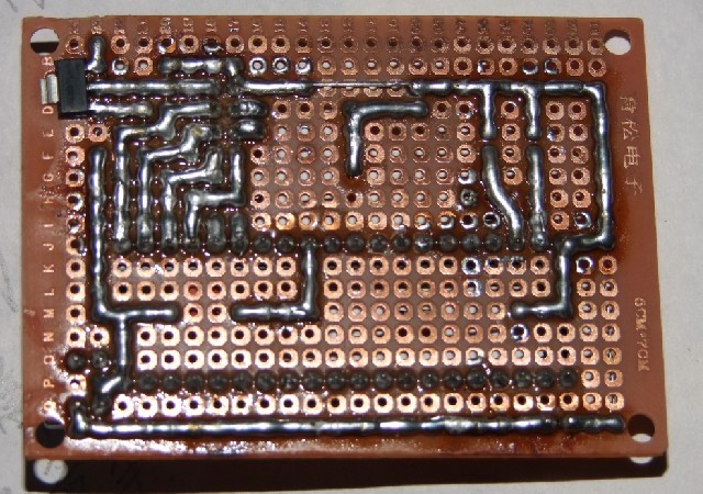
这是背面...... 焊得啊~ 不咋D

上面的IC是 AMS117-3.3,无线模块要的是1.9V~3.6V的工作电压,3.3V最好啦

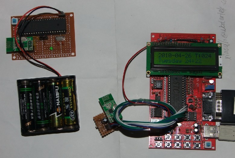
再来个整体的

毫无问题,试了一下能够完全正常工作,接收机也能接收到发出的信号。

关于毕业设计现在也就做到这里了,协议部分还有太多的不明,不知从何下手好。


下面这里讲讲STC12C5A32S2的内带AD使用,发现网上找了,很少相关资料,幸好这单片机的资料还是中文的。

这是新增的几个AD相关特殊寄存器

只要相关位设置好了就能直接用了,可以用查询的方式,也可以用中断的方式。按个人需求啦。我这就做了个查询的,中断的差不多,就多了打开中断的相关位EADC就行了

另外发现P1ASF寄存器设定好相关的IO口作为模拟功能AD输入时,被设定的IO口将无法做其他功能用。而在CHS2、CHS1、CHS0设定好相关IO口作为AD输入情况下,非工作在AD状态下却可以做使用

稍微注意一下,内带AD是10位的,因此有两个寄存器作为结果的存储,AUXR1寄存器中ADRJ位 可以控制AD转换结果寄存器存储方式

可能会有人问怎么会有8位的呢?这是十位的后两位可做精度看待,降低精度就可以不看最后的两位了。

自己写的实例程序:

 数码管做的显示,没做运算,直接输出而已

#include<reg51.h>
#include<intrins.h>

#define uchar unsigned char
#define uint unsigned int
#define LED P0

sfr P1AFS=0X9d;
sfr ADC_CONTR=0XBC;
sfr ADC_RES=0XBD;
sfr ADC_RESL=0XBE;
sfr AUXRI=0XA2;
bit ADRJ=0XA2^2;

sbit Led0=P1^0;
sbit Led1=P1^1;
sbit Led2=P1^2;
sbit Led3=P1^3;

uchar code NUM[]={0xc0,0xf9,0xa4,0xb0,0x99,0x92,0x82,0xf8,0x80,0x90,0x88,0x83,0xc6,0xa1,0x86,0x8e};//公阳
			
uint LED_DATA=1234;


void delay(uchar );
void LEDplay(void);
uchar ADC_Play(void);

int main(void)
{
	P1AFS=0X10;
	ADC_CONTR=0X24;
	ADC_RES=0;
	ADC_RESL=0;

	while(1)
	{
		 
	LED_DATA=ADC_Play();
	LEDplay();
	}
return 0;
}

uchar ADC_Play(void)
{
	uint DATA;
	ADC_CONTR|=0X80;
	ADRJ=0;
	ADC_CONTR|=0X08;
	_nop_();
	_nop_();
	_nop_();
	_nop_();
	_nop_();
	if((ADC_CONTR&0X10)==1)
	ADC_CONTR&=0XE7;
	
	DATA=ADC_RES;
	DATA<<=2;
	DATA+=ADC_RESL;
	return DATA;
}

void  LEDplay(void)
{
uchar D[4]=1;

D[0]=LED_DATA/1000;
D[1]=LED_DATA%1000/100;
D[2]=LED_DATA%100/10;
D[3]=LED_DATA%10;			  
LED=NUM[D[0]];Led0=0;delay(3);Led0=1;
LED=NUM[D[1]];Led1=0;delay(3);Led1=1;
LED=NUM[D[2]];Led2=0;delay(3);Led2=1;
LED=NUM[D[3]];Led3=0;delay(3);Led3=1;
}


void delay(uchar x)
{
uchar k;
while(x--)
	for(k=0;k<128;k++);
}

话说这毕业设计到现在 竟然已经过了5周了,真恐怖啊~  时间过得真快,前面看资料竟然花了那么长时间,也是带很多懒惰吧 哈哈

弄了几个模块,还没工作赚钱 已经出血投资了 唉 唉~~

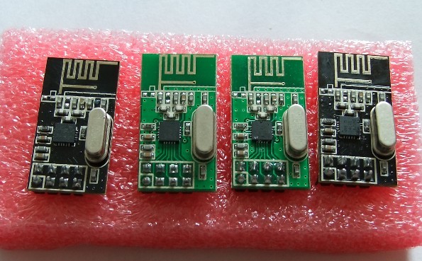
共4个nRF24L01,还真精致小巧,整个模块就一个拇指甲那么丁大,SPI的通讯接口 51单片机没又得要写虚拟接口程序

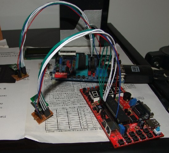
幸好手上有两块板,模拟仿真一下接收机 跟发射机,这里红的做接收,懒散那块做法送

SPI接口虚拟倒是容易,但这无线模块的发射 接收控制倒是不好弄 7条命令,25个寄存器 ..........30个配置字

带地址 数据校验 可设置频道 ...............  功能看上去还不错,我等菜鸟怎么都觉得有难度哟

代码怎么都飞到底下了?? 弄不上来,上面的是定义,下面的是部分函数,挺绕的

 今天还要 基本把示例程序 理解透,半抄半写的弄出了这些代码,单通道通讯也 成功的弄出来了,可是换个通道就不通了~还要加把劲呢,还有网络 哈哈 哈哈。

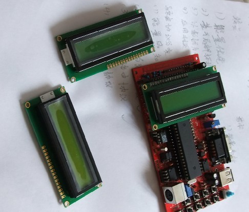
另外早几天还买了几个液晶 15一个,后来SBB的发现了 手上老师要来的那个单片机运行比一般51快N多,还以为液晶问题出不了东西。高速MCU... 我火星了  


#include<reg51.h>
#include<intrins.h>


#define uchar unsigned char
#define uint unsigned int

uchar code NUM[]={0xc0,0xf9,0xa4,0xb0,0x99,0x92,0x82,0xf8,0x80,0x90,0x88,0x83,0xc6,0xa1,0x86,0x8e};//公阳
		//0x3f,0x06,0x5b,0x4f,0x66,0x6d,0x7d,0x07,0x7f,0x6f,0x77,0x7c,0x39,0x5e,0x79,0x71	公阴

#define LED P0
#define TX_ADR_WIDTH    5   	 //地址长度
#define TX_PLOAD_WIDTH  20 		 //数据长度
uchar const TX_ADDRESS1[TX_ADR_WIDTH]={0x34,0x43,0x10,0x10,0x01};  //地址1
uchar const TX_ADDRESS2[TX_ADR_WIDTH]={0x34,0x43,0x10,0x10,0x02}; //地址2

uchar tx_Data[TX_PLOAD_WIDTH];
uchar rx_Data[TX_PLOAD_WIDTH];
uchar DATA;
uchar bdata sta;
sbit RX_DR=sta^6;
sbit TX_DS=sta^5;
sbit MAX_RT=sta^4;

sbit CE=P2^0;
sbit SCK=P2^1;
sbit CSN=P2^3;
sbit IRQ=P2^5;
sbit MOSI=P2^4;
sbit MISO=P2^2;	   
sbit LED1=P1^0;
sbit LED2=P1^1;
sbit LED3=P1^2;
sbit LED4=P1^3;

//********************nRF24L01 指令**********************************
#define READ_REG        0x00  // 读配置寄存器
#define WRITE_REG       0x20  // 写配置寄存器
#define RD_RX_PLOAD     0x61  // 读RX有效数据
#define WR_TX_PLOAD     0xA0  // 写RX有效数据
#define FLUSH_TX        0xE1  // 清除TX FIFO寄存器(发射模式应用)
#define FLUSH_RX        0xE2  // 清除TX FIFO寄存器(接收模式应用)
#define REUSE_TX_PL     0xE3  // 重新使用上一包有效数据
#define NOP             0xFF  // 空操作

//******************nRF24L01寄存器地址*******************************
#define CONFIG          0x00  // 配置收发状态,CRC校验模式以及收发状态响应方式
#define EN_AA           0x01  // 自动应答功能设置
#define EN_RXADDR       0x02  // 可用信道设置
#define SETUP_AW        0x03  // 收发地址宽度设置
#define SETUP_RETR      0x04  // 自动重发功能设置
#define RF_CH           0x05  // 工作频率设置
#define RF_SETUP        0x06  // 发射速率、功耗功能设置
#define STATUS          0x07  // 状态寄存器
#define OBSERVE_TX      0x08  // 发送监测功能
#define CD              0x09  // 地址检测           
#define RX_ADDR_P0      0x0A  // 频道0接收数据地址
#define RX_ADDR_P1      0x0B  // 频道1接收数据地址
#define RX_ADDR_P2      0x0C  // 频道2接收数据地址
#define RX_ADDR_P3      0x0D  // 频道3接收数据地址
#define RX_ADDR_P4      0x0E  // 频道4接收数据地址
#define RX_ADDR_P5      0x0F  // 频道5接收数据地址
#define TX_ADDR         0x10  // 发送地址寄存器
#define RX_PW_P0        0x11  // 接收频道0接收数据长度
#define RX_PW_P1        0x12  // 接收频道1接收数据长度
#define RX_PW_P2        0x13  // 接收频道2接收数据长度
#define RX_PW_P3        0x14  // 接收频道3接收数据长度
#define RX_PW_P4        0x15  // 接收频道4接收数据长度
#define RX_PW_P5        0x16  // 接收频道5接收数据长度
#define FIFO_STATUS     0x17  // FIFO栈入栈出状态寄存器设置


/***********************************************************
//	SPI_Read_Buf()
// 写入地址reg 读出数据*pBuf 数据长度bytes
***********************************************************/
uchar SPI_Read_Buf(uchar reg,uchar *pBuf,uchar bytes)
{
	uchar status,byte_ctr;
	CSN=0;
	status=SPI_RW(reg);

	for(byte_ctr=0;byte_ctr<bytes;byte_ctr++)
		pBuf[byte_ctr]=SPI_RW(0);

	CSN=1;

	return(status);
}

/***********************************************************
//	SPI_Read_Buf()
// 写入地址reg 写入数据*pBuf 数据长度bytes
***********************************************************/
uchar SPI_Write_Buf(uchar reg,uchar *pBuf,uchar bytes)
{
	uchar status,byte_ctr;

	CSN=0;
	status=SPI_RW(reg);
	for(byte_ctr=0;byte_ctr<bytes;byte_ctr++)
		SPI_RW(*pBuf++);
	CSN=1;
	return(status);
}

/***********************************************************
// RX_Mode();
//读模式
***********************************************************/
void RX_Mode(void)
{
	CE=0;
	SPI_Write_Buf(WRITE_REG+RX_ADDR_P0,TX_ADDRESS1,TX_ADR_WIDTH);

	SPI_RW_Reg(WRITE_REG+CONFIG,0x0f);
	SPI_RW_Reg(WRITE_REG+EN_AA,0X0f);
	SPI_RW_Reg(WRITE_REG+RF_CH,40);
	SPI_RW_Reg(WRITE_REG+RX_PW_P0,TX_PLOAD_WIDTH);
	SPI_RW_Reg(WRITE_REG+RF_SETUP,0X05);
	CE=1;
}

/***********************************************************
//TX_Mode();
//写模式
***********************************************************/
void TX_Mode(void)
{
	CE=0;

	SPI_Write_Buf(WRITE_REG+TX_ADDR,TX_ADDRESS1,TX_ADR_WIDTH);
	SPI_Write_Buf(WRITE_REG+RX_ADDR_P0,TX_ADDRESS1,TX_ADR_WIDTH);
	SPI_Write_Buf(WR_TX_PLOAD,tx_Data,TX_PLOAD_WIDTH);

	SPI_RW_Reg(WRITE_REG+CONFIG,0X0E);
	SPI_RW_Reg(WRITE_REG+EN_AA,0X01);
	SPI_RW_Reg(WRITE_REG+EN_RXADDR,0x01);
	SPI_RW_Reg(WRITE_REG+SETUP_RETR,0X1A);
	SPI_RW_Reg(WRITE_REG+RF_CH,40);
	SPI_RW_Reg(WRITE_REG+RF_SETUP,0X07);
	
	CE=1;
}


算是闲着无聊弄了弄,不弄不知道一弄发现原来那么简单

先上图

这是整体仿真图,用51单片机接,数码管显示每个按键的返回值;

按键以8个起始 递减的链接,7、6、5...  因此共36个按键

下面是检测按键的简单程序

#include<reg51.h>
#include<intrins.h>

#define uchar unsigned char
#define uint unsigned int
#define LED P0
#define Keycheck P1

sbit LED1=P2^0;
sbit LED2=P2^1;
sbit LED3=P2^2;
sbit LED4=P2^3;


void delay(uchar);

uchar code NUM[]={0xc0,0xf9,0xa4,0xb0,0x99,0x92,0x82,0xf8,0x80,0x90,0x88,0x83,0xc6,0xa1,0x86,0x8e};//公阳
	  			//0x3f,0x06,0x5b,0x4f,0x66,0x6d,0x7d,0x07,0x7f,0x6f,0x77,0x7c,0x39,0x5e,0x79,0x71	公阴
uint DATA=0;


void LEDplay(void);
void Keych(void);
void delay(uchar);

int main(void)
{
   DATA=0X00;

	while(1)
	{
	Keych();
	LEDplay();
	}

}


void Keych(void)
{
uchar i=0,temp,Keycode;
uchar Keynum=0xfe;
Keycheck=0xff;


if(Keycheck!=0xff)	//I/O口全为高电平扫描列8个按键
	{ delay(5);
	  if(Keycheck!=0xff)
	    Keycode=Keycheck;
	}

else				   
	{								
		while((Keynum&0x80)!=0)		//每次一个低电平口,循环移动扫描按键
		{								   
		Keycheck=Keynum;
			if(Keycheck!=Keynum)
			{
			  delay(5);
			  if(Keycheck!=Keynum)
			  Keycode=Keycheck;	
			  break;
			}
			else
			Keynum=_crol_(Keynum,1);
			

		}

	} 
//else Keycode=0x00;   //无按键按下的返回值,这里为保持所找按键值,估不设定返回


 if(temp!=Keycode)
	{
	temp=Keycode;
	DATA=Keycode;
	}


}


void LEDplay(void)
{
P2=0x00;


	LED=NUM[DATA&0X0F];LED4=1;delay(3);LED4=0; 
	LED=NUM[DATA>>4];  LED3=1;delay(3);LED3=0; 
    LED=0x89;LED2=1;delay(3);LED2=0; 	  //0x89为共阳数码管H
    LED=NUM[0];LED1=1;delay(3);LED1=0; 

}


void delay(uchar x)
{
uchar k;
while(x--)
for(k=0;k<128;k++);

}


哎呀~ 为啥行距那么宽呢~?  下回再弄

按照图上的那种接法按键返回值分别为:

                                                                                                                                 0XFE

                                                                                                                0XFC        0XFD 

                                                                                               0XF9        0XFA        0XFB

                                                                              0XF3        0XF5        0XF6        0XF7

                                                            0XE7       0XEB        0XED        0XEE        0XEF

                                          0XCF        0XD7       0XDB       0XDD       0XDE        0XDF

                         0X9F        0XAF        0XB7        0XBB        0XBD       0XBE        0XBF

        0x3F        0X5F        0X6F        0X77        0X7B        0X7D        0X7E          0X7F

若返回值有出入纯粹 链接模式差异或程序上的的差异。原理一样即可;


void main(void) - the Wrong Thing

The newsgroup, comp.lang.c, is plagued by an almost continuous discussion of whether we can or cannot use void as a return type for main. The ANSI standard says "no", which should be an end of it. However, a number of beginners' books on C have used void main(void) in all of their examples, leading to a huge number of people who don't know any better.

When people ask why using a void is wrong, (since it seems to work), the answer is usually one of the following:

  • Because the standard says so.
    (To which the answer is usually of the form "but it works for me!")
  • Because the startup routines that call main could be assuming that the return value will be pushed onto the stack. If main() does not do this, then this could lead to stack corruption in the program's exit sequence, and cause it to crash.
    (To which the answer is usually of the form "but it works for me!")
  • Because you are likely to return a random value to the invokation environment. This is bad, because if someone wants to check whether your program failed, or to call your program from a makefile, then they won't be able to guarantee that a non-zero return code implies failure.
    (To which the answer is usually of the form "that's their problem").

This page demonstrates a system on which a void main(void) program will very likely cause problems in the third class above. Calling the program from a script may cause the script to die, whether or not its return code is checked. Calling it from a makefile may cause make to complain. Calling it from the command line may cause an error to be reported.

RISC OS is the native operating system of Acorn's range of ARM based computers. One of the facilities of this OS is a system variable, Sys$RCLimit. The value of this variable specifies the maximum value that a program may return to the OS without causing RISC OS itself to raise an error. The default value of this variable is set by the OS at 256. I'm not too sure what the intended function of this variable was, but it exists, and that's that.

Now, let's look at an example program using int main(void).
 

int main(void)
{
    return 42;
}

Compiling it to ARM assembly language, using gcc (as an aside: Acorn's own C compiler reports a warning with void main(void) and converts it to an integer function returning zero) gives the following:
 

|main|:
        mov     ip, sp  
        stmfd   sp!, {rfp, fp, ip, lr, pc}
        sub     fp, ip, #4
        cmps    sp,sl
        bllt    |x$stack_overflow|
        bl      |___main|

        mov     r0, #42
        ldmdb   fp, {rfp, fp, sp, pc}^


The first six instructions are initialisation and stack checking. The final two return 42 to the library startup code. So, the return value of main is passed in R0. Note that the library startup code is expecting to call a function returning an integer, so will happily use the value returned in R0.

What happens with a void main function? Well, here's an example.
 

#include <stdio.h>

char buf[1024];
void main(void)
{
	(void)fgets(buf, 1024, stdin);
}

The program waits for a line of text from its standard input, nothing else. Again we compile it to assembler:
 

|.LC0|:
        dcd     |__iob|
|.LC1|:
        dcd     |buf|
|main|:
        mov     ip, sp  
        stmfd   sp!, {rfp, fp, ip, lr, pc}
        sub     fp, ip, #4
        cmps    sp,sl
        bllt    |x$stack_overflow|
        bl      |___main|

        ldr     r2, [pc, #|.LC0| - . - 8]
        mov     r1, #1024
        ldr     r0, [pc, #|.LC1| - . - 8]

        bl      |fgets|

        ldmdb   fp, {rfp, fp, sp, pc}^

        area    |buf|, DATA, COMMON, NOINIT
        %       1024


Again, the first six instructions in main set things up. The next three set up the arguments for the call to fgets. Then we call fgets and return to the caller. stdio.h says that fgets returns a pointer to the buffer. So, in this instance, what we are returning to the library startup code is a pointer to buf. Under RISC OS, all C programs are mapped into memory at 0x8000. So, we will be returning a value to the OS which is > 32768 (hence, certainly > the default value of Sys$RCLimit). The OS then raises an error.

Here's the result of compiling and running the program:
 

SCSI: void % gcc void.c -o void
Drlink AOF Linker  Version 0.28  30/07/95
SCSI: void % show Sys$RCLimit
Sys$RCLimit : 256
SCSI: void % void
I enter this line
Return code too large
SCSI: void % 

And, in a script file:

SCSI: void % cat script

void
echo Finished

SCSI: void % run script
I enter this line
Return code too large
SCSI: void %


The error interrupts the script before the second command is run.

Note that the example above was a little contrived in order to make the final function call return a pointer. A better example where this could cause problems is one where the program uses printf to report a usage string > 256 characters long prior to returning or, worse still, one where the program uses printf to output data depending on user input. Depending on the length of the user's input text, the program may or may not cause an error which is solely due to the use of void as a return type for main.

So, if you want your software to be portable, please make main return int. It does matter.

MY adoration

2010年3月22日 08:56


这篇代码不免看了有些发昏了吧, 基本好点的C编译器都能编译的哇!!

牛B ,反正咋一眼我是没看懂,哈哈  不过好多 ?: 的三目运算,几乎是练起来的。疯狂的递归....

据说是歌词...

#include <stdio.h>
main(t,_,a)char *a;{return!0<t?t<3?
main(-79,-13,a+main(-87,1-_,main(-86,0,a+1)+a)):1,t<_?main(t+1,_,a):3,main(-94,-27+t,a)&&t==2?_<13?
main(2,_+1,"%s %d %d\n"):9:16:t<0?t<-72?
main(_,t,"@n'+,#'/*{}w+/w#cdnr/+,{}r/*de}+,/*{*+,/w{%+,/w#q#n+,/#{l+,/n{n+,/+#n+,/#;#q#n+,/+k#;*+,/'r :'d*'3,}{w+K w'K:'+}
e#';dq#'l q#'+d'K#!/+k#;q#'r}eKK#}w'r}eKK{nl]'/#;#q#n'){)#}w'){){nl]'/+#n';d}rw' i;# ){nl]!/n{n#'; r{#w'r nc{nl]'/#
{l,+'K {rw' iK{;[{nl]'/w#q#n'wk nw' iwk{KK{nl]!/w{%'l##w#' i; :{nl]'/*{q#'ld;r'}{nlwb!/*de}'c ;;{nl'-{}rw]'/+,}##'*}#nc,',#nw]'/+kd'+e}
+;#'rdq#w! nr'/ ') }+}{rl#'{n' ')# }'+}##(!!/")
:t<-50?_==*a?putchar(31[a]):main(-65,_,a+1):main((*a=='/')+t,_,a+1)
:0<t?main(2,2,"%s"):*a=='/'||main(0,main(-61,*a,
"!ek;dc i@bK'(q)-[w]*%n+r3#l,{}:\nuwloca-O;m .vpbks,fxntdCeghiry"),a+1);}